D88A42 User's Guide
Introduction
This guide is designed to provide comprehensive information to help you install, configure, and operate both the hardware and software components of the D88A42. This device provides reliable data acquisition and control solutions for various applications, including industrial automation, process control, and laboratory measurements. Whether you're a technician setting up hardware connections, a software developer integrating the provided libraries, or an end-user operating the system through the control panel, this documentation is your complete reference.
Who Should Use This Documentation?
This guide is intended for:
- System Integrators: Setting up the hardware for field applications.
- Engineers and Technicians: Installing and configuring the system.
- Software Developers: Using the C# and Python libraries for custom solutions.
- End Users: Operating the system through the provided software interface.
How This Documentation Is Organized
This guide is divided into the following main sections:
Hardware Documentation:
- Details physical connections, relay usage, and input/output configurations.
- Provides wiring diagrams and safety considerations.
Software Documentation:
- Explains the usage of the control panel and device settings.
- Describes channel configuration, reading inputs, controlling outputs, and system resets.
Library Documentation:
- Offers programming guides for the provided C#/.NET and Python libraries.
- Includes code examples, API references, and best practices.
Warnings and Safety Notice
Your safety and the safety of others are of the utmost importance. Please read and understand the following warnings and safety notices before installing, configuring, or operating the en · Z · em system. Failure to adhere to these guidelines may result in injury, equipment damage, or voiding of warranties.
General Safety Warnings
- Qualified Personnel Only: Installation, wiring, and maintenance of this system should be performed only by qualified personnel with knowledge of electrical safety standards and practices.
- Disconnect Power Before Servicing: Always disconnect all power sources before working on the system to avoid electric shock or unintentional equipment operation.
- Avoid Contact with Live Circuits: Never touch exposed terminals or conductors while the system is powered. High voltages may be present, posing a risk of severe injury or death.
- Proper Grounding Is Mandatory: Ensure that the system is properly grounded to prevent electrical shock and ensure safe operation.
Electrical Safety Notices
- High Voltage Warning: The relays and connectors may carry voltages up to 120VAC or 30VDC. Extreme caution should be used when connecting or disconnecting devices under load.
-
Use Proper Wiring Practices:
- Use appropriately rated wires and connectors for your application.
- Insulate all exposed conductors to prevent accidental contact or short circuits.
-
Current Limits Must Not Be Exceeded:
- Relay Contacts: 120VAC @ 10 Amps max or 30VDC @ 2 Amps max.
- Exceeding these ratings may cause equipment failure, fires, or personal injury.
Fire and Equipment Safety
- Do Not Bypass Safety Features: All protective covers, fuses, and safety mechanisms should remain in place and be functional.
- Prevent Overheating: Install the system in a well-ventilated area. Do not obstruct airflow or mount it near heat sources.
- Use Proper Fusing: To prevent fires, always use the recommended fuse ratings and circuit protection devices.
Installation Environment Warnings
- Indoor Use Only: The en · Z · em system is intended for indoor, dry environments.
- Avoid Moisture and Flammable Environments: Do not expose the system to rain, liquids, or flammable atmospheres.
- Temperature Range: Operate only within the specified temperature range (0°C to 50°C) to avoid damage.
Relay and Wiring Precautions
- Double-Check Connections: Ensure that all wiring matches the diagrams provided. Incorrect wiring can result in unintended device operation or system damage.
- NO/NC Confusion: Be aware of the relay’s Normally Open (NO) and Normally Closed (NC) connections. Incorrect usage can lead to unintended device activation.
- Power Down When Connecting Loads: Always disconnect power when wiring high-voltage or high-current loads to the relays.
Additional Notes
- Voltage and Current Ratings: Ratings provided are maximum allowable values under ideal conditions. Always verify load requirements and consult the relay datasheet if unsure.
- Use Protective Equipment: Wear safety glasses and appropriate personal protective equipment (PPE) during installation and maintenance.
Disclaimer:
Failure to comply with these safety instructions can result in injury, death, or significant property damage. Edward Schmitz Software assumes no responsibility for damages arising from misuse, improper installation, or failure to follow safety guidelines.
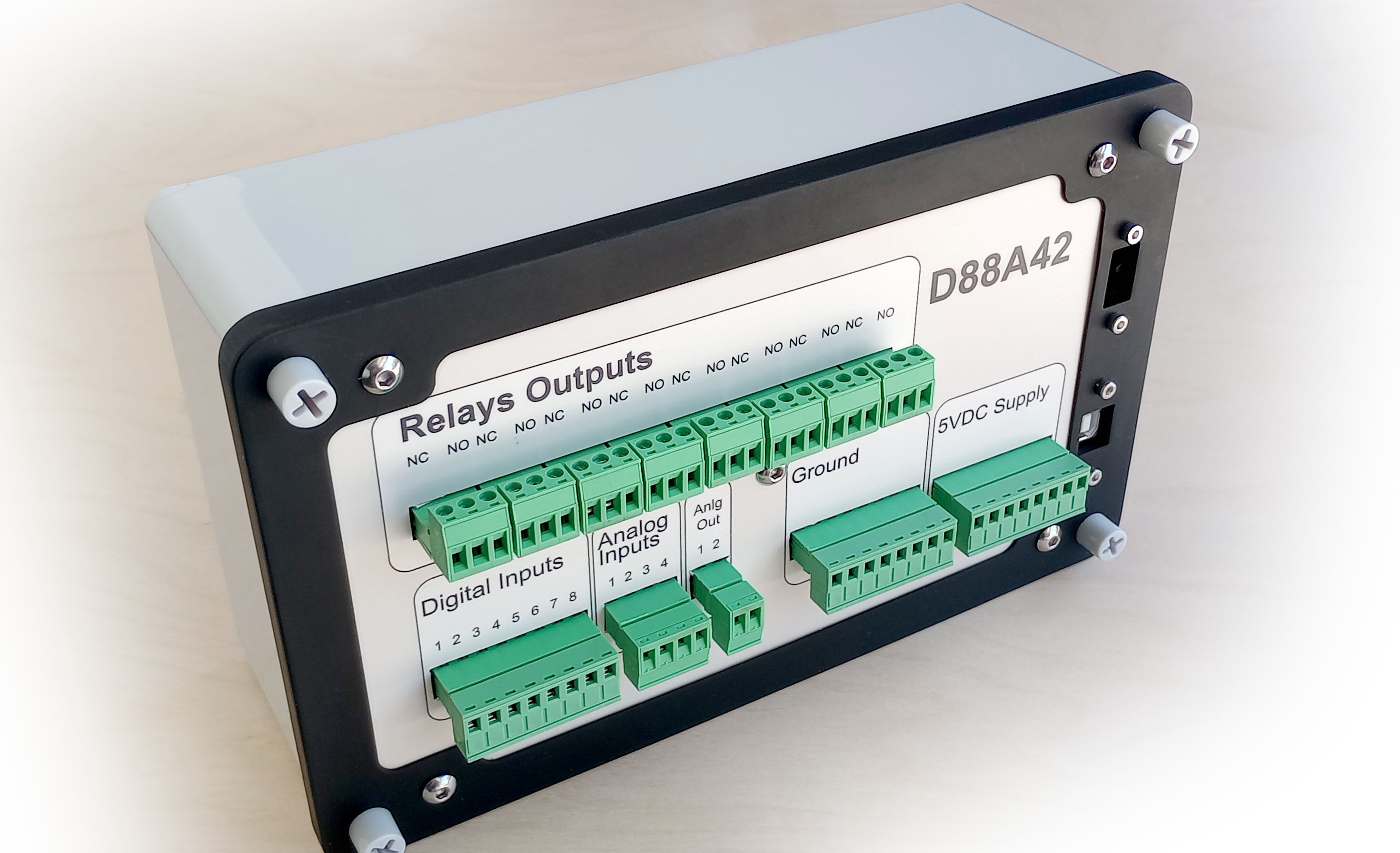
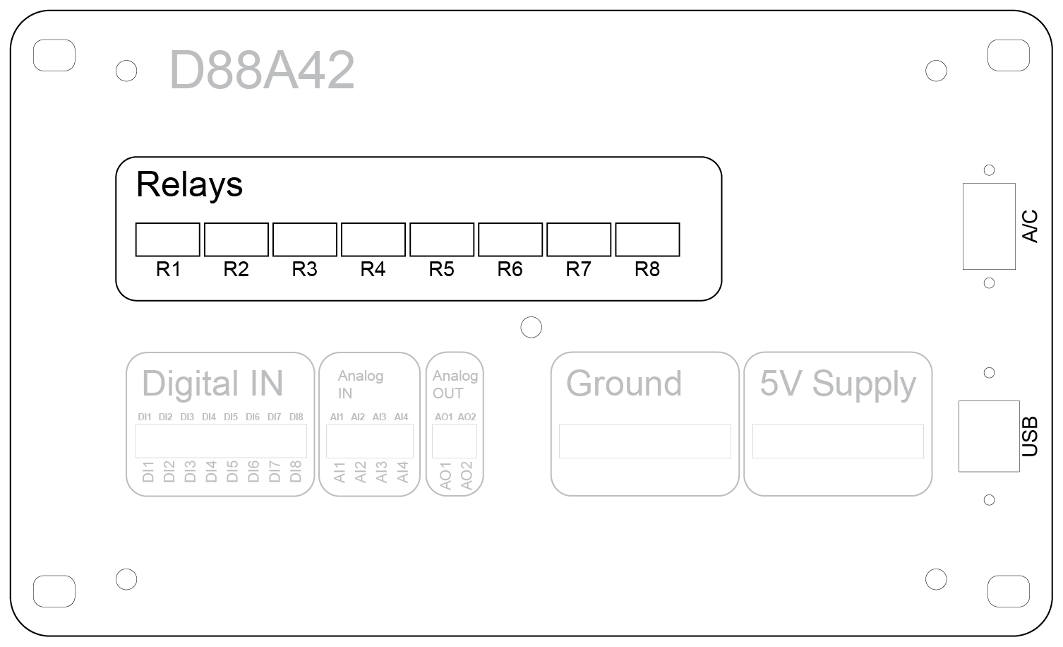
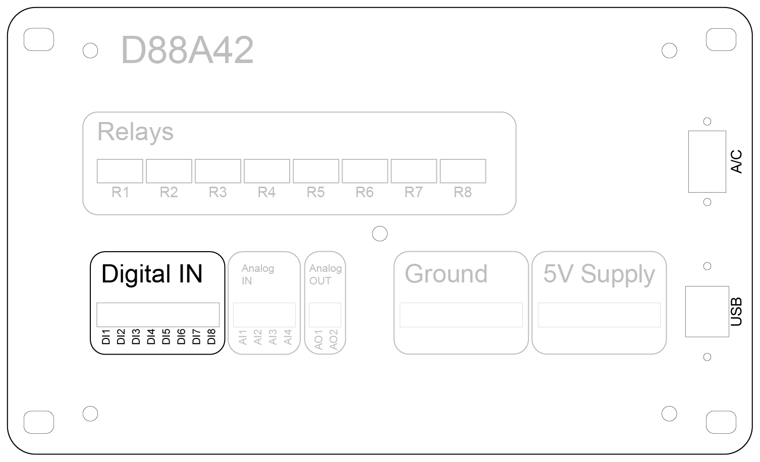
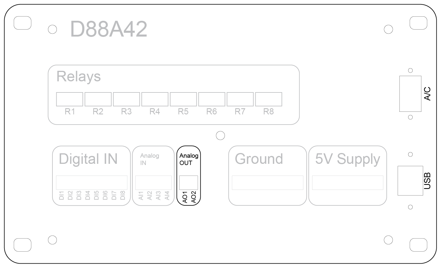
Front Panel
The front panel of the D88A42 device provides clear labeling and organized sections for easy access to all I/O connections, power inputs, and relay controls. The panel layout is designed for intuitive operation and straightforward installation.
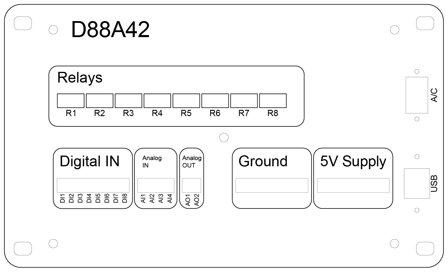
Relay Outputs (R1–R8)
- Function: Controls external devices by switching loads up to 120VAC @ 10 Amps or 30VDC @ 2 Amps.
- Relay Indicators: Each relay has an associated LED indicator (if applicable) to display the current relay state (activated or deactivated).
- Connection Type: Single Pole Double Throw (SPDT) terminals offering Normally Open (NO) and Normally Closed (NC) options.
Digital Inputs (DI1–DI8)
- Input Range: OFF: 0 to 0.5 VDC, ON: 3 to 5 VDC.
- Purpose: Reads digital signals from switches, sensors, or other external devices.
- Common Ground: All digital inputs share a common ground terminal for simplified wiring.
Analog Inputs (AI1–AI4)
- Voltage Range: Standard: 0 to 10 VDC; With voltage dividers: 0 to 40 VDC (jumper configurable).
- Application: Monitors sensors and devices that output variable voltages (e.g., temperature sensors, pressure transducers).
- Calibration & Filtering: Software-configurable for improved accuracy and stable readings.
Analog Outputs (AO1–AO2)
- Output Range: 0 to 5 VDC.
- Function: Provides control signals for external equipment requiring analog input (e.g., motor speed controllers or signal generators).
- Calibration: Outputs can be scaled to represent engineering units for precise control.
Ground Terminal
- Purpose: Provides a common reference point for all input and output connections.
- Recommendation: Always connect external device grounds to this terminal to ensure proper operation and noise reduction.
5V Supply Terminal
- Usage: Powers external sensors or logic-level devices.
- Caution: Ensure the total load does not exceed the specified current limit to prevent damage.
Power and Communication Ports
-
AC Input (Top Right):
- Provides primary power to the device.
- Use proper mains-rated cables and follow safety guidelines when connecting.
-
USB Port (Bottom Right):
- Facilitates software communication, firmware updates, and device configuration.
- Supports direct connection to a PC for control and monitoring.
Relay Usage
The D88A42 device is equipped with eight relays (R1–R8), enabling control of external devices by switching AC or DC loads. Each relay is a Single Pole Double Throw (SPDT) type, providing flexibility to use either the Normally Open (NO) or Normally Closed (NC) contacts depending on the application.
Relay Functions
Relays serve as electrically controlled switches. They allow the device to control higher-voltage circuits without direct electrical connection to the internal electronics. Common uses include:
- Turning external equipment (motors, lights, pumps) on and off
- Switching between two circuits (using NO and NC contacts)
- Implementing safety interlocks or control logic
Contact Terminals
Each relay has three terminals:
-
NO (Normally Open):
- Default state: Open (disconnected) when the relay is inactive.
- Energized state: Closed (connected), allowing current to flow.
- Use Case: Control devices that should be off until activated.
-
NC (Normally Closed):
- Default state: Closed (connected) when the relay is inactive.
- Energized state: Open (disconnected), stopping current flow.
- Use Case: Maintain devices in an on state until commanded off (e.g., fail-safe systems).
-
COM (Common):
- Shared terminal that switches between the NO and NC contacts depending on relay state.
- Connect your external power supply to this terminal for controlling the load.
Relay Specifications
-
Voltage and Current Ratings:
- AC Loads: Up to 120 VAC at 10 Amps
- DC Loads: Up to 30 VDC at 2 Amps
- Switching Time: Approximately 10 milliseconds from command to contact closure.
- Electrical Isolation: Relays provide galvanic isolation between the device's internal circuitry and external circuits.
Wiring Guidelines
Select the Appropriate Contact:
- Use NO for loads that should only receive power when the relay is activated.
- Use NC for loads that should remain powered unless the relay is activated.
Power Connections:
- Connect the COM terminal to the external power source.
- Connect the NO or NC terminal to your load, depending on desired behavior.
Isolation Considerations:
- Do not connect the external power source’s ground to the device’s internal ground.
- The relay contacts are completely isolated from the device's ground and internal electronics to ensure safe and independent external circuits.
General Safety:
- Ensure wiring is properly insulated and secured.
- Never exceed the relay’s specified voltage or current ratings.
- Power off all circuits before making or altering connections.
Example Applications
- Low-Voltage Signal Switching: Activate control inputs on PLCs or other controllers.
- High-Power Load Switching: Control AC motors, lighting, or heaters.
- Fail-Safe Systems: Use NC contacts for devices that should be powered unless a fault condition occurs.
5VDC Start/Stop Control

Uses the relay to manage start and stop commands using the device's internal 5VDC supply.
Internal 5VDC Supply Connection

Example of using the device’s internal 5VDC supply for relay activation.
24VDC External Supply Connection

Controls a 24VDC device with an external power source.
120VAC External Supply Connection
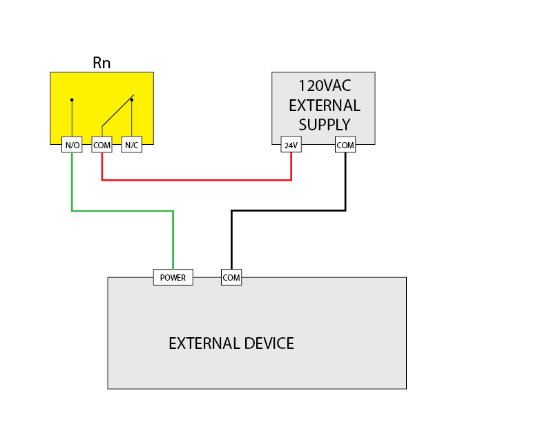
Switches 120VAC loads for industrial applications.
Dry Contact Signal Connection

Demonstrates using the relay as a dry contact for low-current signals.
Digital Input Usage
The digital input (DI) section of the device provides eight input channels labeled DI1 through DI8. These inputs are designed to detect the presence of an external voltage signal to monitor the state of external devices such as switches, sensors, or relay outputs.
Input Voltage Levels
OFF (Low State): 0 to 0.5 VDC
ON (High State): 3 to 5 VDC
Any voltage within the ON range will be detected as an active high signal, while voltages within the OFF range will be considered inactive.
Connection Instructions
- Each digital input has a corresponding terminal labeled DI1 through DI8.
- Do not connect external grounds to the device’s ground terminal. The digital inputs share a common internal reference through the device.
- To activate an input, apply a voltage signal within the ON range to the input terminal.
Example Applications
- Connecting external relay outputs to monitor device states.
- Reading the state of mechanical switches for user control inputs.
- Detecting output signals from sensors with compatible voltage levels.
Important Notes
- Exceeding the maximum input voltage can damage the device. Do not apply more than 5 VDC to the digital input terminals.
- Ensure the wiring is secure and that external circuits adhere to the specified voltage ranges.
- Inputs are designed for signal detection only and should not be used to power external devices.
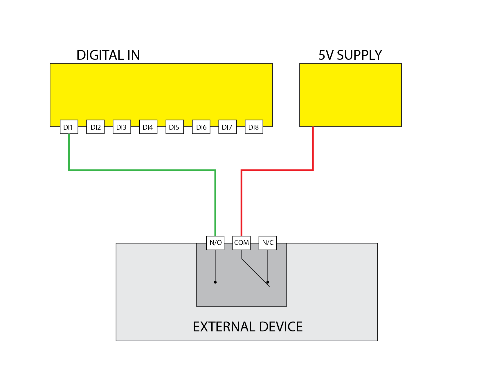
Digital Input 5V Signal
Demonstrates using the digital input to read a 5V signal.
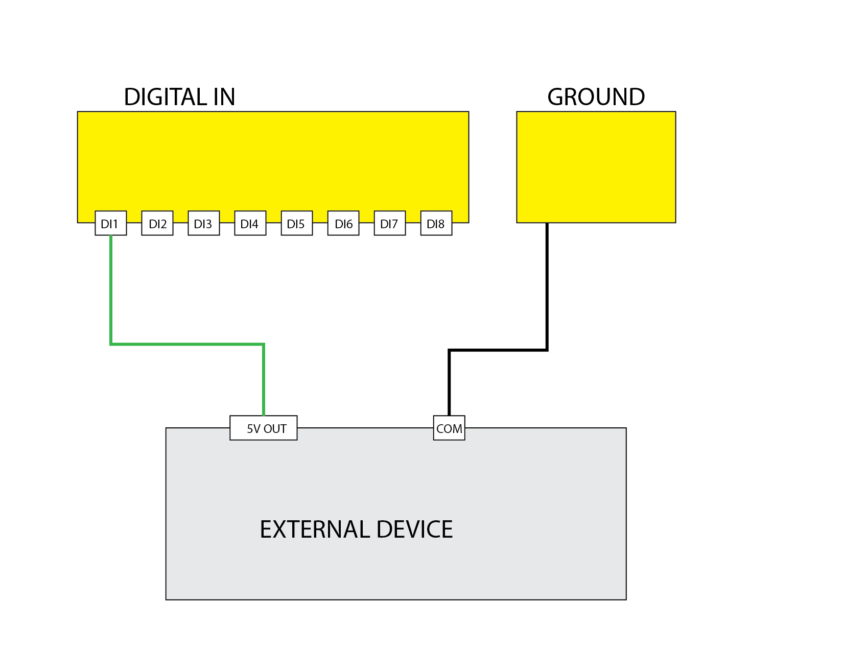
Digital Input Closed Contact
Demonstrates using the digital input to read a closed contact.
Analog Input Usage
The device provides four analog input (AI) channels labeled AI1 through AI4. These inputs are designed to measure voltage signals from external sensors or equipment, allowing the user to monitor various analog parameters such as temperature, pressure, or voltage levels.
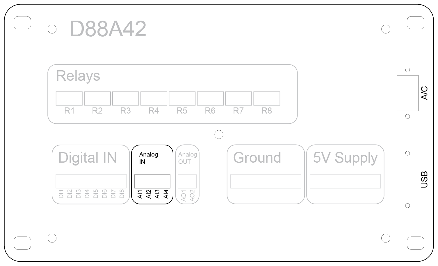
Input Voltage Ranges
- Standard Range: 0 to 10 VDC (default configuration)
- Extended Range: 0 to 40 VDC (when internal voltage dividers are enabled via jumper configuration)
Important: Do not apply voltages exceeding the configured range. Applying voltages beyond these limits may damage the device.
Connection Instructions
- Connect the positive signal line to the desired analog input terminal (AI1–AI4).
- Do not connect the external circuit ground to the device’s ground terminal. The analog inputs share an internal reference.
- When using the extended range (up to 40 VDC), ensure that the internal jumper is correctly set to enable the voltage divider.
Calibration and Filtering
- Calibration: The software allows users to apply calibration settings to correct electrical offsets and scale input signals to engineering units. For example, a voltage input can be calibrated to display temperature, pressure, or other real-world units.
- Filtering: Software-configurable filtering options help stabilize readings by smoothing out rapid signal fluctuations.
Example Applications
- Monitoring output from pressure transducers, temperature sensors, or potentiometers.
- Reading voltage signals from external control systems or industrial equipment.
- Measuring supply voltage levels in battery-powered systems.
Best Practices and Safety Tips
- Verify the polarity of connections before applying power.
- Use shielded cables for long wire runs to reduce electrical noise and improve measurement accuracy.
- Ensure the input voltage never exceeds the specified maximum to prevent permanent damage.
- Avoid connecting inductive loads or high-voltage sources directly to the analog inputs.
0 to 10 Volt Reading
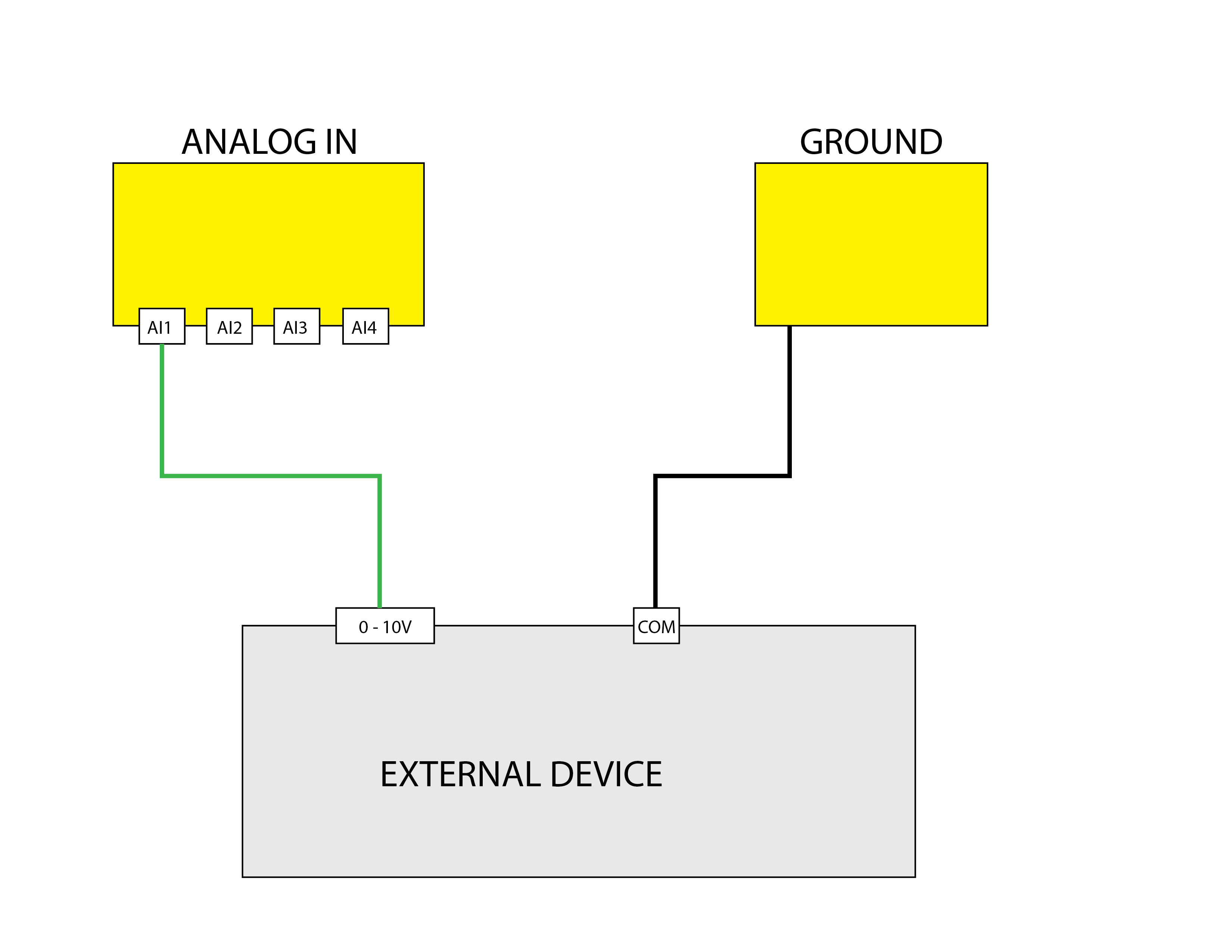
Uses the Analog Input A1 to read a value between 0 and 10V.
0 to 20 High Voltage Reading
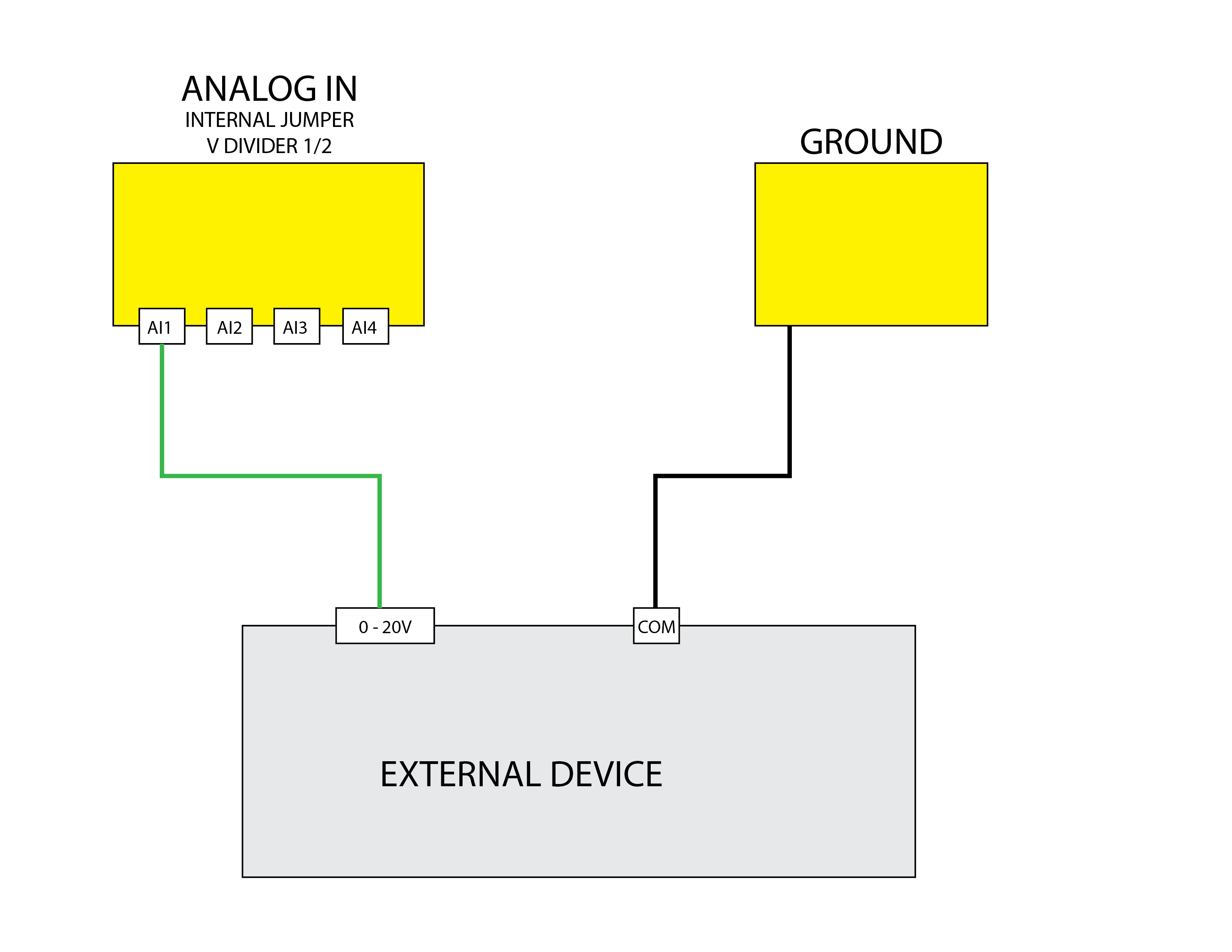
Uses the Analog Input A1 to read a high voltage value between 0 and 20V.
mAmp Reading
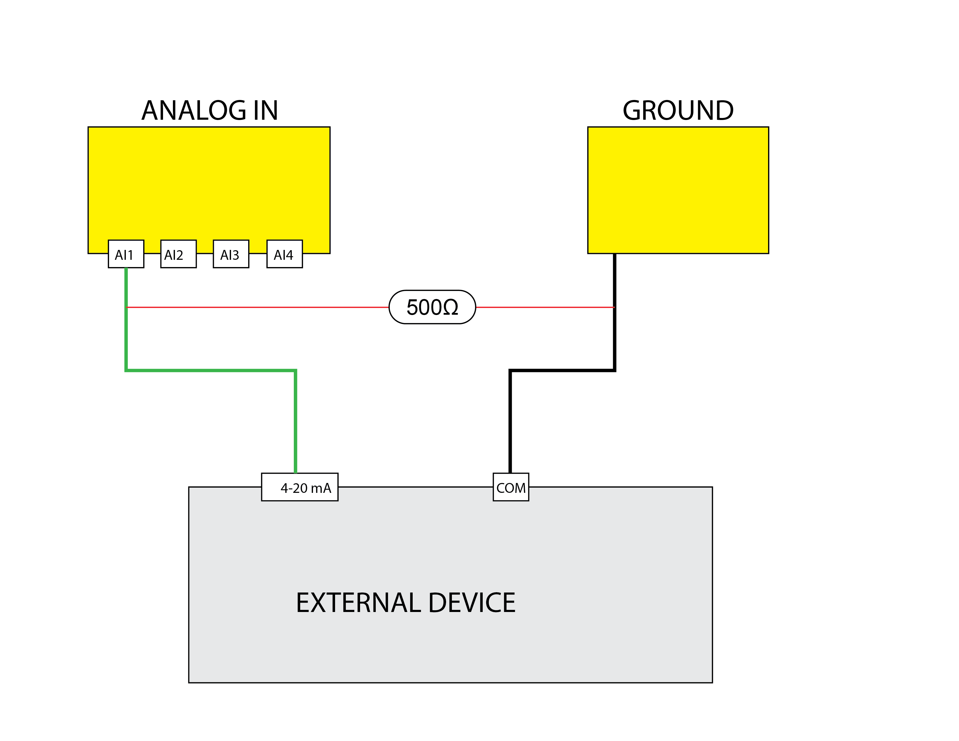
Uses the Analog Input A1 to read a milliamp value between 0 and 20mA. The
Analog Output Usage
The device features two analog output channels, labeled AO1 and AO2, allowing users to send precise voltage signals to external equipment for control or simulation purposes.
Output Voltage Range
0 to 5 VDC (default and maximum range)
Note: The analog outputs are designed for low-current signaling applications and are not intended for directly powering loads.
Connection Instructions
Follow these steps to connect the analog outputs:
- Connect the positive input terminal of the external device to AO1 or AO2.
- Do not connect the external circuit ground to the device’s ground terminal. The outputs are isolated internally to prevent ground loops.
- Ensure the receiving device can accept a 0–5 VDC input signal.
Calibration and Scaling
Calibration:
- The software provides calibration options to correct minor voltage deviations and ensure accurate output levels.
- Operators can apply scaling to convert desired engineering units into the appropriate voltage output.
-
For example, if controlling a device that expects a 0–100 PSI input signal:
- The software can scale a 0–5 VDC output to represent the 0–100 PSI range.
Usage of Calibration:
- Enter the desired target unit (e.g., temperature, pressure, or speed) in the software.
- The system automatically adjusts the voltage output to correspond to the input units.
Common Applications
- Controlling variable-speed drives (VFDs) or proportional valves.
- Providing setpoints to external controllers or process equipment.
- Simulating sensor outputs for system testing and development.
- Driving instrumentation equipment requiring a reference voltage.
Best Practices and Warnings
- Always confirm the input range of the external device before connecting the analog output.
- Avoid drawing excessive current from the analog outputs. Use buffer amplifiers if the load requires higher current.
- Never short the analog outputs to ground as this may damage the output circuitry.
- Use shielded cables for long runs to prevent noise interference.
- Perform regular calibration checks to maintain measurement accuracy.